Saturday, September 29, 2012

Netlist Extraction (Part 1)

Up to this point all the effort has been to make the settings required for CAM350 to operate on the database. But before that can happen there are 2 more operations that must be performed on the database itself to prepare it for netlist extraction.

  1. If there are areas of Poured Copper on the outer layers you may need to Convert Draws to Raster Polygons before a netlist can be successfully extracted.


First, try extracting the netlist without taking this step. The file has been saved to this point so skip to step 2 (convert draws to flashes) and then go on to extract the netlist. 
If netlist extraction is not successful reload the last saved version and Convert Draws to Raster Polygons as follows:

Select Utilities/Polygon Conversion > Draw To Raster Poly.

The Command Status prompts for a selection or window.

Do Not use a window to define the area to be processed if that area will also include traces. Only areas of copper flood should be selected. Objects will become highlighted as they are selected. If there are a large number of polygons, consider creating a separate layer for just the copper. Perform the conversion then copy the copper to the correct associated layer.


When the instances of polygon have been selected, click the RMB to begin the conversion process. A dialog box will appear. Click OK with the LMB to start conversion.
When the Command Status display prompts for a selection again the process is complete.
Terminate the command by clicking the RMB.


The next blog post will show a demonstration of the Draw to Raster Poly command.

Wednesday, September 26, 2012

Layer Sets (for Blind and Buried Vias) - LAB


Select Tables/Layer Sets > Blind and Buried pull down menu option.


Click on the Thru Drill button and select CAM_DemoNC1-6.D from the Layer List window.


Change the Name entry to LyrSet_1-4.


Click on number “1” from the list with the LMB. 
Add CAM_DemoL1.PHO to the list. 
Do the same for numbers 2, 3, & 4 with CAM_DemoL2, L3 &, L4.PHO respectively.


Click on the Drill Data button with the LMB to pop up the layer list. 
Click on the appropriate layer with the LMB to andselect CAM_DemoNC1-4.D from the Layer List window.


Click the Add button with LMB to create a new layer set name.


Change the Name entry to LyrSet_3-4.


Click on number “1” from the list with the LMB. 
Add CAM_DemoL3.PHO to the list. 
Add CAM_DemoL4.PHO to number 2.


Click on the Drill Data button with the LMB to pop up the layer list. 
Click on the appropriate layer with the LMB to andselect CAM_DemoNC3-4.D from the Layer List window.


Save your work now using File/Save.

Monday, September 24, 2012

Layer Sets (for Blind and Buried Vias) - Video

Watch this video to view a demonstration of the Layer Set operation for Blind and Buried Vias:

Saturday, September 22, 2012

Layer Sets (for Blind and Buried Vias)


When Blind and Buried vias are used in a design CAM350 must be instructed as to the relationships between the Drill Tables and the layers they are associated with. A Layer Set Table is used for this purpose.


The layer set table is accessed from the Tables/Layer Sets > Blind and Buried pull down menu option.

Click on the Thru Drill button to pop up a Layer List window.


Select the layer associated with the final stage (through) drill using the LMB 
(in this case “CAM_DemoNC1-6.D”).


Set up the table for the fist (blind) layer set as follows:
1. Change the Name entry to reflect the layer set (1-4)


2. Click on a number from the list with the LMB. A Layer List window will pop up. 
     Click on a layer from the list that is to be added in the numbered layer position. 
     In the following example we can see that layers 1 and two have already been selected.    
     Adding CAM_DemoL4.PHO will complete the Blind layer set.


3. The drill data for this layer set is added in the same manner as for the thru drill. 
     Click on the Drill Data button with the LMB to pop up the layer list. 
     Click on the appropriate layer with the LMB to select it .


Set up the table for the second (buried) layer set as follows:
1. Change the Name entry to reflect the layer set (3-4)


2. Click on a number from the list with the LMB. A Layer List window will pop up. 
     Click on a layer from the list that is to be added in the numbered layer position. 
     In the following example we can see that layers 3 has already been selected. 
     Adding CAM_DemoL4.PHO will complete the Buried layer set.


3. The drill data for this layer set is added in the same manner as for the thru drill. 
     Click on the Drill Data button with the LMB to pop up the layer list. 
     Click on the appropriate layer with the LMB to select it .


This completes the Layer Set setup.


Thursday, September 20, 2012

NC Tool Table - LAB


Before proceeding with this step note the relative sizes of the “holes” in the Work Area display on the NC Drill layers (14,15 & 16)


Open NC Tool Table from the Tables pull down menu.


First, set the units to Millimeters
(Note that the Size column still indicates Mil – disregard)


Enter the Drill Sizes and Usage into the table. 
Refer to the layer definitions in the Readme text file in the Gerber file directory for drill tool sizes and plating.


Use the Tool Table pull down menu to change between Tables for the 3 Drill layers.


Click OK to exit the NC Tool Table menu.


What does the Work Area display for layers 14 15 & 16 look like now?


Save your work using File/Save.

Wednesday, September 19, 2012

NC Tool Table - Video

Watch a demonstration of the PADS Drill Macro here:

Sunday, September 16, 2012

NC Tool Table


The NC Tool Table contains drill sizes.
Get to the NC tool table from the Tables pull down menu.


There will be a Tool Table that corresponds to each NC Drill layer.
This happens automatically when the files are auto-imported.

In this case there is a table for each layer set. (drill pair).


To enter drill sizes in a table:

  1. Select the desired table from the Tool Table pull down menu.
  2. Set the units as desired.
  3. Enter the drill size in the Size column (Note that the column headingremains as Mils even though millimeters are set as Dialog units).Refer to the Drill Report for the drill tool sizes.
  4. Set the Usage checkbox to indicate holes are Plated or Unplated
  5. Do steps 1 through 3 for each drill set table.


For PowerPCB and Allegro users there are also macros available that will automatically load the Tool Table. The macro will not, however, work with multiple drill sets.


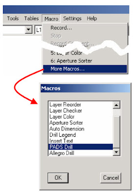
Instead of entering the NC drill sizes manually as described earlier in this section use the Macro pull-down menu to select and run the Pads Drill macro.

The next blog post will demonstrate the use of the Pads drill macro.


Friday, September 14, 2012

Aligning Layers (Move Alignment) - LAB


Now, turn on all layers except the two partial drill layers (CAM_DemoNC1-4.D and CAM_DemoNC3-4.D).


From the Edit pull down menu select Move.

  • Note the instructions in the Command Status area of the Status Bar that will assist you in stepping through this procedure.

Press the “W” key to select Group Mode (Note the shape of the cursor).

  • Note that the lower left tooling hole of the through drill layer (CAM_DemoNC1-6.D) is already located at the origin. Therefore we’ll be moving only the Board area layers (CAM_DemoNC1-4.D and

CAM_DemoNC3-4.D must be off).

Remember: to perform a netlist comparison, the CAM origin must be located in the same location as it is in the PCB design.


Remember: layers may be freely turned on or off to facilitate selection.


Place the cursor in one corner of the window and click with the LMB.


Drag the cursor to the opposite corner and click again with the LMB.


All selected elements that will move will become highlighted.


Commit to the selection by clicking the RMB (note the cursor change shape) or make a new selection as previously described.


Click on the Source alignment (use the lower left tooling hole) object using the LMB.


Remember the alignment object must be present in both the reference layer and the layer to be aligned.


Command Status changes to:
Move the cursor to the Destination alignment point and click once with the LMB. 


Complete the move by clicking the RMB.

Use the “Move” command in the same way to line up the remaining partial drill layers with the rest of the layers.


Save your work using File/Save (the file is saved to the name you assigned with the Save As command previously in section 6)


Use the Cam_Demo_Aligned.CAM file as a reference if you have any questions.

Experiments:

  • Try moving some objects using “Grid Snap” in stead of “Object Snap”.
  • Toggle the Grid display using the “V” key.
  • Change the grid using Grid Snap pull down menu. What happens when you select Panoramic from the View menu?
  • What happens in the Panoramic window when you zoom in and out?
  • What happens to the Work Area display when you click the cursor in the Panoramic Window?

Thursday, September 13, 2012

Aligning Layers (Move Alignment) - Video


To view a demonstration of the Move Alignment Procedure, watch this video:

Monday, September 10, 2012

Aligning Layers (Move Alignment)


Another means of alignment is by physically moving a layer or group of layers, 
again using “Object Snap” as the means of alignment.


From the Edit pull down menu, select Move.

Follow the directions that will appear in the Command Status area of the Status Bar.


Press the “W” key to select Group Mode (Note the shape of the cursor).
In this mode the cursor is used to form a window around the group to be moved. 
Place the cursor in one corner of the window and click with the LMB. 
Drag the cursor to the opposite corner and click again with the LMB. 
All selected elements will become highlighted.


Remember: 
Layers may be freely turned on or off to facilitate selection.


Commit to the selection by clicking the RMB (note the cursor shape) 
or  make a new selection as previously described.


The Command Status changes to:


Make sure the “Snap to Object” button is pressed.


Click on the Source alignment object using the LMB.


Remember the alignment object must be present in both the reference layer
and the layer to be aligned.


The Command Status changes to:
Note that a “virtual selection” box appears with the cursor at the location of the Source alignment point.


Move the cursor to the Destination alignment point and click once with the LMB. 
The “virtual selection” will snap to align with that point.
Complete the move by clicking the RMB.


Remember: 
To perform a netlist comparison, the CAM origin must be located in the same location as it is in the PCB design. Use a combination of Object Snap and Grid Snap, if necessary, to align all layers with the origin.


The next blog post will show how to align layers and move their alignment.
Keep subscribing to my blog!

Friday, September 7, 2012

Aligning Layers (Layer-to-Layer Alignment) - LAB


The layers and drills have been deliberately offset.


First we’ll align layer 1 with layer 2 using Edit/Layers > Align.


Turn off all but layers 1 and 2. 
(These layers should be CAM_DemoL1.PHO and CAM_DemoL2.PHO respectively).
  • CAM_DemoNC3-4.DNote the instructions in the Command Status area of the Status Bar that will assist you in stepping through this procedure.
  •  Make sure the “Snap to Object” (“Z”) button is pressed on the Status Bar.

Select the lower left mounting hole on layer 2. 

Click on the object using the LMB (Left mouse button) then “Commit” to this selection by clicking the RMB (right mouse button.).
  • Note how the “Page Up” and “Page Down” keys can be used to increase or decrease the “pick” area of the cursor.
  • Note that layers may be freely turned on or off to facilitate selection.
Select the complimentary object on the layer to be aligned with the LMB then commit to the object with the RMB.

  • Note the fact that this procedure cannot be undone. 

A warning message allows an opportunity to abort if necessary.


Clicking the RMB a second time completes the operation aligning the two layers.

Thursday, September 6, 2012

Aligning Layers (Layer-to-Layer Alignment) - Video

Here's a demonstration of the Layer-to-Layer Alignment procedure:


Monday, September 3, 2012

Aligning Layers (Layer-to-Layer Alignment)


Once loaded, the layers and drills may not be aligned.
(For this demonstration they have been deliberately offset).


Before any meaningful analysis can be done all the elements must be aligned to each other and also to the origin.


Note: 
It is essential that the origin of the CAM350 elements match the origin of PCB design file.


Alignment can be performed in two ways. 
The first, Edit/Layers > Align

Follow the directions that will appear in the Command Status area of the Status Bar.

Select the point on the “reference layer” to which the “offset layer” layer will be aligned. This object must be present on both layers. 

Choose a mounting hole or other prominent feature.

Note that layers may be freely turned on or off to facilitate selection.

Make sure the “Snap to Object” button is pressed.
Click on the object using the LMB (Left mouse button) then “Commit” to this selection by clicking the RMB (right mouse button.).

The Command Status changes to:

Select the complimentary object on the layer to be aligned with the LMB then commit to the object with the RMB.

Clicking the RMB a second time completes the operation aligning the two
layers.

Note that this procedure cannot be undone. 
A warning message allows an opportunity to abort if necessary.


Friday, August 31, 2012

Layer Table and Defining Layers - LAB


Use the Tables pull down menu or the “y” hotkey to access the Layer Table


Refer to the layer definitions in the Readme text file in the Gerber file directory for the correct layer Types.


Assign Draw and Flash colors. Then exit the menu.


Experiment

  • Can you figure out what the file types are by looking at the layers?
  • What happens to the colors in the Layer Bar?
  • Can you change the layer names?
  • Turn off all but two layers. Set one of the layers to Ref using the status button. 
           What happens when you redraw the display? 


  • What happens if you try to select an object on the REF layer? 

           (Use Edit/Move or Copy as a selection device).

Thursday, August 30, 2012

Layer Table and Defining Layers - Video


Here is a demonstration of the Layer Table setup procedure:


Monday, August 27, 2012

Layer Table and Defining Layers


Use the Tables pull down menu or the “y” hotkey to access the Layer Table.


The layer table is used to set the layer Type, and assign Draw and Flash colors. 
It can also be used to set the Active layer (the layer that remains on when all others are turned off) and the Top layer (the layer that redraws last and therefore appears “on top” in the screen display). 


The Data column indicates whether or not the layer contains any data.


(Note that the layer numbers correspond to the numbers in the layer bar.)


Layer types are selected from a pull down menu that is accessed from a cell in Type
column of the layer’s row.
Select the appropriate layer definition from the available options.

Note: 
Whether a plane is positive or negative has nothing to do with its electrical characteristics
but with whether the photo file represents a positive or negative image. “Positive Plane”
layers are processed the same as “Internal” layers

Colors are selected from a chart that pops up by clicking the Draw or Flash cells. 
Color selection is purely a matter of user choice. Try to select familiar draw colors that will help you recognize layers on sight. Choose a different (preferably dark) color for flashes.
In addition to the ability to turn layers On and Off the Layer Table can set a layer to “Ref
(for reference). In this condition objects on a layer can be viewed but can not be selected.


A video demonstrating Layer Table and Defining Layers will be posted on the next blog post.


Saturday, August 25, 2012

Ordering Layers - LAB


From the Edit pull down menu, select Layers/Reorder.

(Note the layer order as it appears in the Active Layer pulldown window.)

On the Reorder Layers popup menu, click on a line item and drag it to a new location in the layer order.

When all layers have been placed in the desired order, click on the Renumber button.

Exit by clicking on the OK button with the LMB.

(Note the layer order as it now appears in the Active Layer pulldown
window.)

Friday, August 24, 2012

Ordering Layers - Video

Here's how ordering layers is done in CAM350:


Tuesday, August 21, 2012

Ordering Layers


Each Gerber file that has been imported represents a “Layer” of the design. 


If we could see a cross section of the design we would see that each of these layers occupies a unique physical space from top to bottom. Putting the layers in a specific order is more of a user choice issue than an operational requirement. In fact, the order means nothing. It’s simply conducive to the sanity of the user.


From the Edit pull down menu, select Layers/Reorder.
When the Reorder Layers popup menu appears, 
click on a line item and drag it to a new location in the layer order.

Before Reorder


After Reorder


When all layers have been placed in the desired order, click on the Renumber button.

This will assign a new layer number that corresponds to the numbers on the layer bar.
Exit this menu by clicking on the OK button with the LMB.

The next blog will show a demonstration of the Layer Reordering procedure.


Sunday, August 19, 2012

Importing Gerber and Drill Data - LAB

Use File/New to begin a new CAM350 session.


Select File/Import/Auto Import and set a path to the PCB2CAM350/
Gerber directory.

Set the button for Metric, then select Finish
Cam350 will automatically select and load the Gerber and NC drill files.

During the loading process a message will pop up warning of “Unassigned Tools. 
This concerns drill sizes which have not yet been set and is normalbehavior.

Note: Because this demonstration board has Blind and Buried vias the
             message pops up 3 times. Once for each drill set.

Experiments:
  • What happens when you load the files with set the button set to English?
  • What happens when you select Next instead of Finish?
Make sure the Gerber and Drill files are loaded correctly before proceeding.

Use the Settings/Units pull down menu and select Metric.

Use the File/Save As command at this point to open a new CAM350 database for this design. Set the path to your practice area and assign the file a unique name (i.e. don’t use the same name as the Demo files).

Use the CAM_Demo_Offset.CAM file as a reference if you have any questions.

Note: the dot “CAM” file extension denotes a native CAM350 formatted file.
            CAM350 files are Opened using File/Open.

Saturday, August 18, 2012

Importing Gerber and Drill Data - Video

Here's how to import gerber and drill data using CAM350:


Wednesday, August 15, 2012

Importing Gerber and Drill Data

Use File/New to begin a new CAM350 session.

Then, select File/Import/Auto Import

Set a path to the directory that contains the Gerber and NC Drill data. 

Select the appropriate button for English or Metric, then select Finish

Cam350 will automatically select and load the Gerber and NC drill files 
(selecting Next allows the user to select the files that will be loaded).


If you’re a PowerPCB user you will see a pop up warning of “Unassigned Tools.


This concerns drill sizes which have not yet been set and is normal behavior.


A video tutorial to show this process will be posted on the next blog.
Subscribe to this blog and learn more about using CAM350 for PCB Designers.